
EATON 189973 4NA Yardımcı Kontaktör
Marka: Eaton
0,00₺
 10.000₺ ve üzeri alışverişlerinize özel teklif.


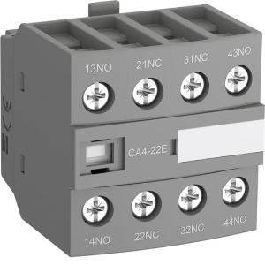
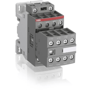
EATON 189973 DILER-40-EA (230V50HZ,240V60HZ) 4NA Mini Yardımcı Kontaktör (AC bobin)
| Datasheet – DILER-40-EA(230V50HZ,240V60HZ) | |||
| Part no. | DILER-40-EA(230V50HZ,240V60HZ) | ||
| Article no. | 189973 | ||
| Catalog No. | 189973 | ||
| 2110PIC-29 | |||
| Delivery program | |||
| Product range | DILER Mini-contactors | ||
| Application | Contactor relays | ||
| Description | with interlocked opposing contacts | ||
| Connection technique | Screw terminals | ||
| Rated operational current | |||
| Conventional free air thermal current, 1 pole | |||
| Open | |||
| at 50 °C | Ith =Ie | A | 10 |
| AC-15 | |||
| 220 V 230 V 240 V | Ie | A | 6 |
| 380 V 400 V 415 V | Ie | A | 3 |
| Contacts | |||
| N/O = Normally open | 4 N/O | ||
| Contact sequence | 210S001 | ||
| Code number and version of combination | |||
| Distinctive number | 40E | ||
| For use with | …DILE | ||
| Actuating voltage | 230 V 50 Hz, 240 V 60 Hz | ||
| Voltage AC/DC | AC operation | ||
| Instructions | Contact numbers to EN 50011 Coil terminal markings to EN 50005 | ||
| Technical data | |||
| General | |||
| Standards | IEC/EN 60947, EN 60947-5-1, VDE 0660, UL, CSA | ||
| Lifespan, mechanical | |||
| AC operated | Operations | x 106 | 10 |
| Maximum operating frequency | Operations/h | 9000 | |
| Climatic proofing | Damp heat, constant, to IEC 60068-2-78 Damp heat, cyclic, to IEC 60068-2-30 | ||
| Ambient temperature | |||
| Open | °C | -25 – +50 | |
| Enclosed | °C | – 25 – 40 | |
| Mounting position | |||
| Mounting position | As required, except vertical with terminals A1/A2 at the bottom | ||
| Mounting position | 230K003 | ||
| Mechanical shock resistance (IEC/EN 60068-2-27) | |||
| Half-sinusoidal shock, 10 ms | |||
| Basic unit with auxiliary contact module | g | ||
| N/O contact | g | 10 | |
| N/C contact | g | 8 | |
| Degree of Protection | IP20 | ||
| Protection against direct contact when actuated from front (EN 50274) | Finger and back-of-hand proof | ||
| Altitude | m | max. 2000 m | |
| Weight | |||
| AC operated | kg | 0.17 | |
| Terminal capacities | mm2 | ||
| Screw terminals | |||
| Solid | mm2 | 1 x (0.75 – 2.5) 2 x (0.75 – 2.5) | |
| Flexible with ferrule | mm2 | 1 x (0.75 – 1.5) 2 x (0.75 – 1.5) | |
| Solid or stranded | AWG | 18 – 14 1 x (18 – 14) 2 x (18 – 14) | |
| Stripping length | mm | 8 | |
| Terminal screw | M3.5 | ||
| Pozidriv screwdriver | Size | 2 | |
| Standard screwdriver | mm | 0.8 x 5.5 1 x 6 | |
| Max. tightening torque | Nm | 1.2 | |
| Contacts | |||
| Interlocked opposing contacts to ZH 1/457, including auxiliary contact module | Yes | ||
| Rated impulse withstand voltage | Uimp | V AC | 6000 |
| Overvoltage category/pollution degree | III/3 | ||
| Rated insulation voltage | Ui | V AC | 690 |
| Rated operational voltage | Ue | V AC | 600 |
| Safe isolation to EN 61140 | |||
| between coil and auxiliary contacts | V AC | 300 | |
| between the auxiliary contacts | V AC | 300 | |
| Rated operational current | A | ||
| Conventional free air thermal current, 1 pole | |||
| Open | |||
| at 50 °C | Ith =Ie | A | 10 |
| AC-15 | |||
| 220 V 230 V 240 V | Ie | A | 6 |
| 380 V 400 V 415 V | Ie | A | 3 |
| 500 V | Ie | A | 1.5 |
| DC current | |||
| Notes | Switch-on and switch-off conditions based on DC-13, time constant as specified. | ||
| DC L/R ≦ 15 ms | |||
| Contacts in series: | A | ||
| 1 | 24 V | A | 2.5 |
| 2 | 60 V | A | 2.5 |
| 3 | 110 V | A | 1.5 |
| 3 | 220 V | A | 0.5 |
| Control circuit reliability | Failure rate | λ | -8, < one failure at 100 million operations (at Ue = 24 V DC, Umin = 17 V, Imin = 5.4 mA) |
| Short-circuit rating without welding | |||
| Maximum overcurrent protective device | |||
| 220 V 230 V 240 V | PKZM0 | 4 | |
| 380 V 400 V 415 V | PKZM0 | 4 | |
| Short-circuit protection maximum fuse | |||
| 500 V | A gG/gL | 6 | |
| 500 V | A fast | 10 | |
| Current heat loss at Ith | |||
| AC operated | W | 1.1 | |
| Magnet systems | |||
| Voltage tolerance | |||
| AC operated | |||
| Single-voltage coil 50 Hz and dual-voltage coil 50 Hz, 60 Hz | Pick-up | x Uc | 0.8 – 1.1 |
| Dual-frequency coil 50/60 Hz | Pick-up | x Uc | 0.85 – 1.1 |
| Power consumption | |||
| AC operation | |||
| Single-voltage coil 50 Hz and dual-voltage coil 50 Hz, 60 Hz | Pick-up | VA | 25 |
| Single-voltage coil 50 Hz and dual-voltage coil 50 Hz, 60 Hz | Sealing | VA | 4.6 |
| Single-voltage coil 50 Hz and dual-voltage coil 50 Hz, 60 Hz | Sealing | W | 1.3 |
| duty factor | % DF | 100 | |
| Changeover time at 100 % US (recommended value) | |||
| AC operated closing delay | ms | 14 – 21 | |
| AC operated N/O contact opening delay | ms | 8 – 18 | |
| AC operated With auxiliary contact module Max. closing delay | ms | 45 | |
| Rating data for approved types | |||
| Auxiliary contacts | |||
| Pilot Duty | |||
| AC operated | A600 | ||
| DC operated | P300 | ||
| General Use | |||
| AC | V | 600 | |
| AC | A | 10 | |
| DC | V | 250 | |
| DC | A | 0.5 | |
| Design verification as per IEC/EN 61439 | |||
| Technical data for design verification | |||
| Rated operational current for specified heat dissipation | In | A | 6 |
| Heat dissipation per pole, current-dependent | Pvid | W | 0.4 |
| Equipment heat dissipation, current-dependent | Pvid | W | 0 |
| Static heat dissipation, non-current-dependent | Pvs | W | 1.8 |
| Heat dissipation capacity | Pdiss | W | 0 |
| Operating ambient temperature min. | °C | -25 | |
| Operating ambient temperature max. | °C | 50 | |
| IEC/EN 61439 design verification | |||
| 10.2 Strength of materials and parts | |||
| 10.2.2 Corrosion resistance | Meets the product standard’s requirements. | ||
| 10.2.3.1 Verification of thermal stability of enclosures | Meets the product standard’s requirements. | ||
| 10.2.3.2 Verification of resistance of insulating materials to normal heat | Meets the product standard’s requirements. | ||
| 10.2.3.3 Verification of resistance of insulating materials to abnormal heat and fire due to internal electric effects | Meets the product standard’s requirements. | ||
| 10.2.4 Resistance to ultra-violet (UV) radiation | Meets the product standard’s requirements. | ||
| 10.2.5 Lifting | Does not apply, since the entire switchgear needs to be evaluated. | ||
| 10.2.6 Mechanical impact | Does not apply, since the entire switchgear needs to be evaluated. | ||
| 10.2.7 Inscriptions | Meets the product standard’s requirements. | ||
| 10.3 Degree of protection of ASSEMBLIES | Does not apply, since the entire switchgear needs to be evaluated. | ||
| 10.4 Clearances and creepage distances | Meets the product standard’s requirements. | ||
| 10.5 Protection against electric shock | Does not apply, since the entire switchgear needs to be evaluated. | ||
| 10.6 Incorporation of switching devices and components | Does not apply, since the entire switchgear needs to be evaluated. | ||
| 10.7 Internal electrical circuits and connections | Is the panel builder’s responsibility. | ||
| 10.8 Connections for external conductors | Is the panel builder’s responsibility. | ||
| 10.9 Insulation properties | |||
| 10.9.2 Power-frequency electric strength | Is the panel builder’s responsibility. | ||
| 10.9.3 Impulse withstand voltage | Is the panel builder’s responsibility. | ||
| 10.9.4 Testing of enclosures made of insulating material | Is the panel builder’s responsibility. | ||
| 10.10 Temperature rise | The panel builder is responsible for the temperature rise calculation. Eaton will provide heat dissipation data for the devices. | ||
| 10.11 Short-circuit rating | Is the panel builder’s responsibility. The specifications for the switchgear must be observed. | ||
| 10.12 Electromagnetic compatibility | Is the panel builder’s responsibility. The specifications for the switchgear must be observed. | ||
| 10.13 Mechanical function | The device meets the requirements, provided the information in the instruction leaflet (IL) is observed. | ||
| Technical data ETIM 7.0 | |||
| Low-voltage industrial components (EG000017) / Contactor relay (EC000196) | |||
| Electric engineering, automation, process control engineering / Low-voltage switch technology / Contactor (LV) / Contactor relay (ecl@ss10.0.1-27-37-10-01 [AAB716014]) | |||
| Rated control supply voltage Us at AC 50HZ | V | 230 – 230 | |
| Rated control supply voltage Us at AC 60HZ | V | 240 – 240 | |
| Rated control supply voltage Us at DC | V | 0 – 0 | |
| Voltage type for actuating | AC | ||
| Rated operation current Ie, 400 V | A | 3 | |
| Connection type auxiliary circuit | Screw connection | ||
| Mounting method | DIN-rail/screw | ||
| Interface | No | ||
| Number of auxiliary contacts as normally closed contact | 0 | ||
| Number of auxiliary contacts as normally open contact | 4 | ||
| Number of auxiliary contacts as normally closed contact, delayed switching | 0 | ||
| Number of auxiliary contacts as normally open contact, leading | 0 | ||
| With LED indication | No | ||
| Number of auxiliary contacts as change-over contact | 0 | ||
| Manual operation possible | No | ||
| Approvals | |||
| Product Standards | IEC/EN 60947-4-1; UL 508; CSA-C22.2 No. 14-05; CE marking | ||
| UL File No. | E29184 | ||
| UL Category Control No. | NKCR | ||
| CSA File No. | 012528 | ||
| CSA Class No. | 3211-03 | ||
| North America Certification | UL listed, CSA certified | ||
| Specially designed for North America | No | ||
| Characteristics | |||
| 210O001 | |||
| 1: Suppressor 2: Auxiliary contact module | |||
| <a | |||
Değerlendirme yazabilmek için soturum açmalısınız
İlgili ürünler
Orijinal fiyat: 693,60₺.242,76₺Şu andaki fiyat: 242,76₺.
Orijinal fiyat: 1.682,40₺.588,84₺Şu andaki fiyat: 588,84₺.
Orijinal fiyat: 1.682,40₺.588,84₺Şu andaki fiyat: 588,84₺.
Değerlendirmeler
Henüz değerlendirme yapılmadı.