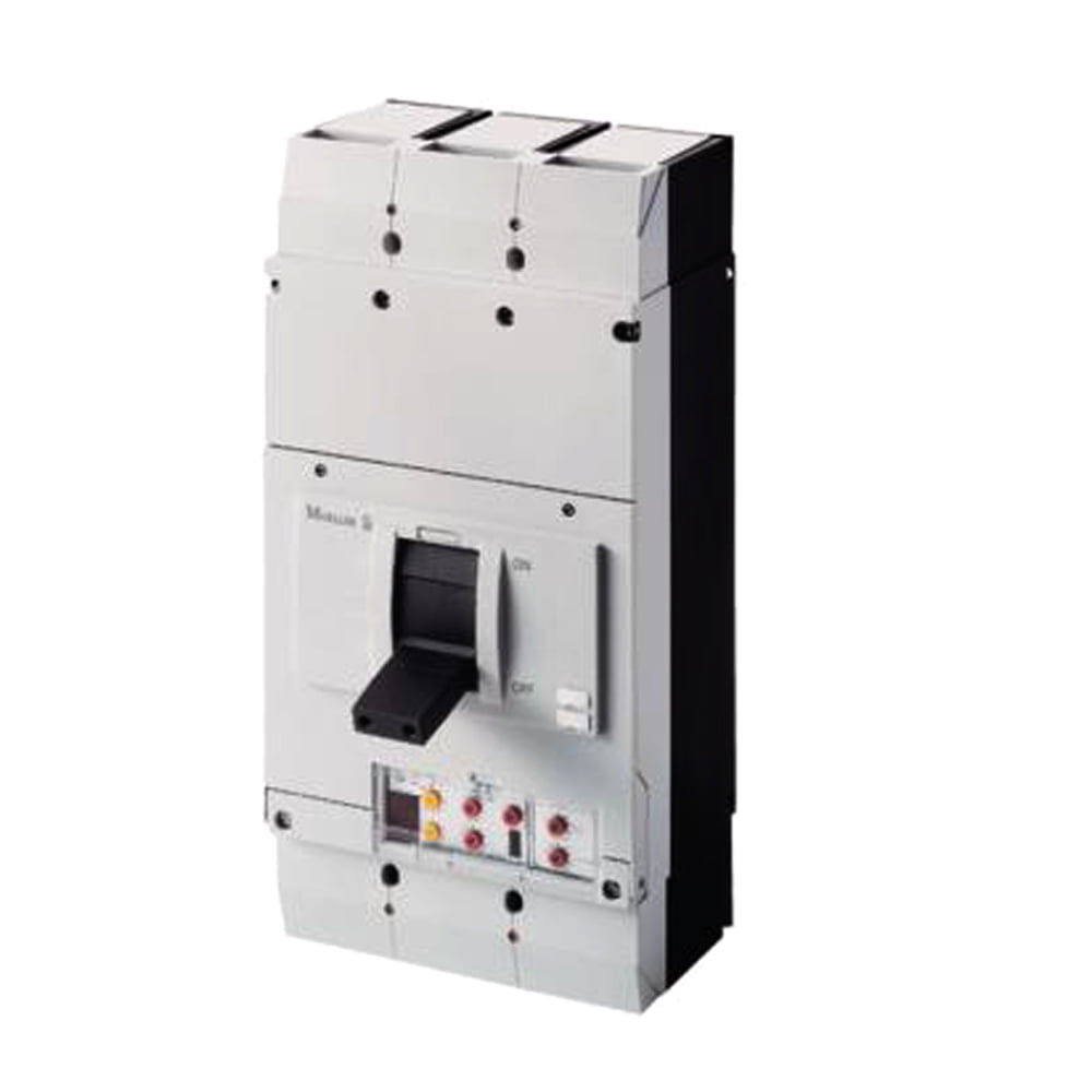
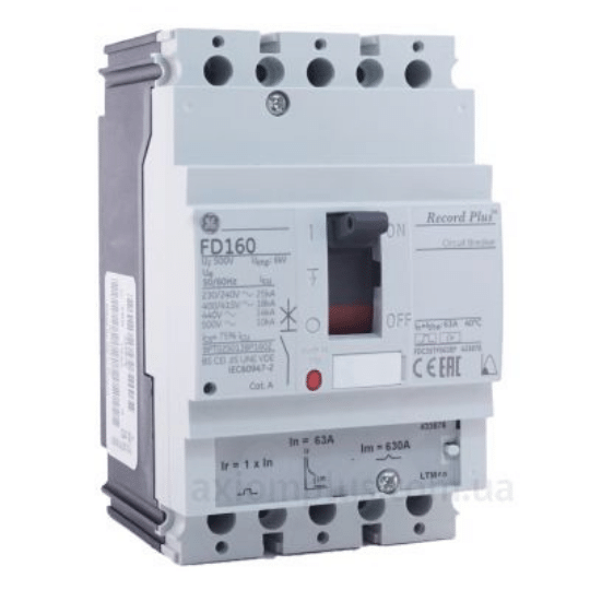
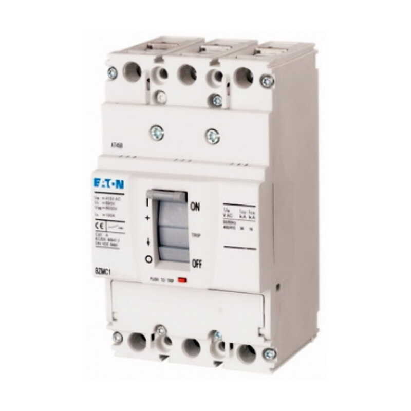
EATON 265770 3x1000A 50kA Kompakt Şalter
Marka: Eaton
Orijinal fiyat: 104.071,80₺.36.425,13₺Şu andaki fiyat: 36.425,13₺.
 10.000₺ ve üzeri alışverişlerinize özel teklif.
EATON 265770 NZMN4-VE1000 3x1000A 50kA Kompakt Şalter (Elektronik-LSI Selektif Koruma)
| Datasheet – NZMN4-VE1000 | ||||
| Part no. | NZMN4-VE1000 | |||
| Article no. | 265770 | |||
| Catalog No. | 265770 | |||
| 1230PIC-715 | ||||
| Similar to illustration | ||||
| Delivery program | ||||
| Product range | Circuit-breaker | |||
| Protective function | Systems, cable, selectivity and generator protection | |||
| Standard/Approval | IEC | |||
| Installation type | Fixed | |||
| Release system | Electronic release | |||
| Construction size | NZM4 | |||
| Description | R.m.s. value measurement and “thermal memory” Adjustable time delay setting to overcome current peaks tr at 6 x Ir also infinity (without overload releases) Adjustable delay time tsd i2t constant function: switchable | |||
| Number of poles | 3 pole | |||
| Standard equipment | Screw connection | |||
| Switching capacity | ||||
| 400/415 V 50 Hz | Icu | kA | 50 | |
| Rated current = rated uninterrupted current | ||||
| Rated current = rated uninterrupted current | In = Iu | A | 1000 | |
| Setting range | ||||
| Overload trip | ||||
| Ir | A | 500 – 1000 | ||
| Short-circuit releases | ||||
| Non-delayed | Ii = In x … | 2 – 12 | ||
| Delayed | Isd = Ir x … | 2 – 10 | ||
| Technical data | ||||
| General | ||||
| Standards | IEC/EN 60947 | |||
| Protection against direct contact | Finger and back of hand proof to VDE 0106 Part 100 | |||
| Climatic proofing | Damp heat, constant, to IEC 60068-2-78 Damp heat, cyclic, to IEC 60068-2-30 | |||
| Ambient temperature | ||||
| Ambient temperature, storage | °C | – 40 – + 70 | ||
| Operation | °C | -25 – +70 | ||
| Mechanical shock resistance (10 ms half-sinusoidal shock) according to IEC 60068-2-27 | g | 15 (half-sinusoidal shock 11 ms) | ||
| Safe isolation to EN 61140 | ||||
| Between auxiliary contacts and main contacts | V AC | 500 | ||
| between the auxiliary contacts | V AC | 300 | ||
| Mounting position | Vertical and 90° in all directions | |||
| 123I692
| With XFI earth-fault release: | |||
| – NZM1, N1, NZM2, N2: vertical and 90° in all directions | ||||
| with plug-in unit | ||||
| – NZM1, N1, NZM2, N2: vertical, 90° right/left | ||||
| with withdrawable unit: | ||||
| – NZM3, N3: vertical, 90° right/left | ||||
| – NZM4, N4: vertical | ||||
| with remote operator: | ||||
| – NZM2, N(S)2, NZM3, N(S)3, NZM4, N(S)4: vertical and 90° in all directions | ||||
| Direction of incoming supply | as required | |||
| Degree of protection | ||||
| Device | In the operating controls area: IP20 (basic degree of protection) | |||
| Enclosures | With insulating surround: IP40 With door coupling rotary handle: IP66 | |||
| Terminations | Tunnel terminal: IP10 Phase isolator and strip terminal: IP00 | |||
| Other technical data (sheet catalogue) | Temperature dependency, Derating | |||
| Circuit-breakers | ||||
| Rated current = rated uninterrupted current | In = Iu | A | 1000 | |
| Rated surge voltage invariability | Uimp | |||
| Main contacts | V | 8000 | ||
| Auxiliary contacts | V | 6000 | ||
| Rated operational voltage | Ue | V AC | 690 | |
| Overvoltage category/pollution degree | III/3 | |||
| Rated insulation voltage | Ui | V | 1000 | |
| Use in unearthed supply systems | V | ≦ 525 | ||
| Switching capacity | ||||
| Rated short-circuit making capacity | Icm | |||
| 240 V | Icm | kA | 105 | |
| 400/415 V | Icm | kA | 105 | |
| 440 V 50/60 Hz | Icm | kA | 74 | |
| 525 V 50/60 Hz | Icm | kA | 53 | |
| 690 V 50/60 H | Ic | kA | 40 | |
| Rated short-circuit breaking capacity Icn | Icn | |||
| Icu to IEC/EN 60947 test cycle O-t-CO | Icu | kA | ||
| 240 V 50/60 Hz | Icu | kA | 50 | |
| 400/415 V 50/60 Hz | Icu | kA | 50 | |
| 440 V 50/60 Hz | Icu | kA | 35 | |
| 525 V 50/60 Hz | Icu | kA | 25 | |
| 690 V 50/60 Hz | Icu | kA | 20 | |
| Ics to IEC/EN 60947 test cycle O-t-CO-t-CO | Ics | kA | ||
| 240 V 50/60 Hz | Ics | kA | 37 | |
| 400/415 V 50/60 Hz | Ics | kA | 37 | |
| 440 V 50/60 Hz | Ics | kA | 26 | |
| 525 V 50/60 Hz | Ics | kA | 19 | |
| 690 V 50/60 Hz | Ics | kA | 15 | |
| Maximum back-up fuse, if the expected short-circuit currents at the installation location exceed the switching capacity of the circuit-breaker. | ||||
| Rated short-time withstand current | ||||
| t = 0.3 s | Icw | kA | 12 | |
| t = 1 s | Icw | kA | 12 | |
| Utilization category to IEC/EN 60947-2 | B | |||
| Lifespan, mechanical(of which max. 50 % trip by shunt/undervoltage release) | Operations | 10000 | ||
| Lifespan, electrical | ||||
| AC-1 | ||||
| 400 V 50/60 Hz | Operations | 3000 | ||
| 415 V 50/60 Hz | Operations | 3000 | ||
| 690 V 50/60 Hz | Operations | 2000 | ||
| AC–3 | ||||
| 400 V 50/60 Hz | Operations | 2000 | ||
| 415 V 50/60 Hz | Operations | 2000 | ||
| 690 V 50/60 Hz | Operations | 1000 | ||
| Max. operating frequency | Ops/h | 60 | ||
| Total break time at short-circuit | ms | 415 V | ||
| Terminal capacity | ||||
| Standard equipment | Screw connection | |||
| Optional accessories | Tunnel terminal connection on rear Strip terminal | |||
| Round copper conductor | ||||
| Tunnel terminal | ||||
| Stranded | ||||
| 4-hole | mm2 | 4 x (50 – 240) | ||
| Bolt terminal and rear-side connection | ||||
| Direct on the switch | ||||
| Stranded | mm2 | 1 x (120 – 185) 4 x (50 – 185) | ||
| Module plate | ||||
| Single hole | min. | mm2 | 1 x (120 – 300) | |
| Single hole | max. | mm2 | 2 x (95 – 300) | |
| Module plate | ||||
| Double hole | min. | mm2 | 2 x (95 – 185) | |
| Double hole | max. | mm2 | 4 x (35 – 185) | |
| Connection width extension | mm2 | |||
| Connection width extension | mm2 | 4 x 300 6 x (95 – 240) | ||
| Al circular conductor | ||||
| Tunnel terminal | ||||
| Stranded | ||||
| 4-hole | mm2 | 4 x (50 – 240) | ||
| Bolt terminal and rear-side connection | ||||
| Module plate | ||||
| Single hole | min. | mm2 | 1 x (185 – 240) | |
| Single hole | max. | mm2 | 2 x (70 – 185) | |
| Module plate | ||||
| Double hole | mm2 | 4 x 50 | ||
| Connection width extension | mm2 | |||
| Connection width extension | mm2 | 2 x 240 6 x (70 – 240) | ||
| Cu strip (number of segments x width x segment thickness) | ||||
| Flat conductor terminal | ||||
| min. | mm | 6 x 16 x 0.8 | ||
| max. | mm | (2 x) 10 x 32 x 1.0 | ||
| Module plate | ||||
| Single hole | mm | (2 x) 10 x 50 x 1.0 | ||
| Bolt terminal and rear-side connection | ||||
| Flat copper strip, with holes | min. | mm | 5 x 25 x 1.0 | |
| Flat copper strip, with holes | max. | mm | (2 x) 10 x 50 x 1.0 | |
| Connection width extension | mm | (2 x) 10 x 80 x 1.0 | ||
| Copper busbar (width x thickness) | mm | |||
| Bolt terminal and rear-side connection | ||||
| Screw connection | M10 | |||
| Direct on the switch | ||||
| min. | mm | 25 x 5 | ||
| max. | mm | 2 x (50 x 10) | ||
| Module plate | ||||
| Single hole | min. | mm | 25 x 5 | |
| Single hole | max. | mm | 2 x (50 x 10) | |
| Module plate | ||||
| Double hole | mm | 2 x (50 x 10) | ||
| Connection width extension | mm | |||
| Connection width extension | min. | mm | 60 x 10 | |
| Connection width extension | max. | mm | 2 x (80 x 10) | |
| Control cables | ||||
| mm2 | 1 x (0.75 – 2.5) 2 x (0.75 – 1.5) | |||
| Design verification as per IEC/EN 61439 | ||||
| Technical data for design verification | ||||
| Rated operational current for specified heat dissipation | In | A | 1000 | |
| Equipment heat dissipation, current-dependent | Pvid | W | 165 | |
| Operating ambient temperature min. | °C | -25 | ||
| Operating ambient temperature max. | °C | 70 | ||
| IEC/EN 61439 design verification | ||||
| 10.2 Strength of materials and parts | ||||
| 10.2.2 Corrosion resistance | Meets the product standard’s requirements. | |||
| 10.2.3.1 Verification of thermal stability of enclosures | Meets the product standard’s requirements. | |||
| 10.2.3.2 Verification of resistance of insulating materials to normal heat | Meets the product standard’s requirements. | |||
| 10.2.3.3 Verification of resistance of insulating materials to abnormal heat and fire due to internal electric effects | Meets the product standard’s requirements. | |||
| 10.2.4 Resistance to ultra-violet (UV) radiation | ||||
Değerlendirme yazabilmek için oturum açmalısınız.


Değerlendirmeler
Henüz değerlendirme yapılmadı.